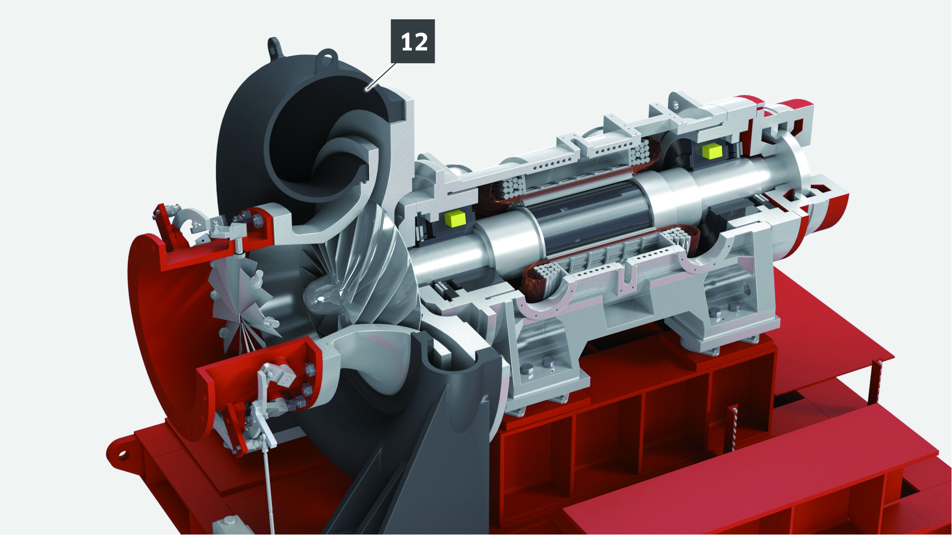

Kawasaki MAG Turbo, designed for wastewater aeration, features a 1.3MW (1,740HP) motor system with active magnetic bearings. This system is compatible with medium voltages, ensuring a wide range of operation and outstanding wire-to-air efficiency.

Kawasaki MAG Turbo, designed for wastewater aeration, features a 1.3MW (1,740HP) motor system with active magnetic bearings. This system is compatible with medium voltages, ensuring a wide range of operation and outstanding wire-to-air efficiency.


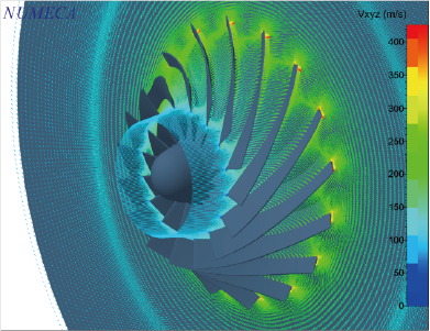
For the development of the MAG Turbo, we applied an analytic method called genetic algorithm to determine the optimal shape of mother impeller.
For each customer’s specification, rotational speed, impeller blade height and thickness are optimally designed, considering all the specified operating conditions to minimize life cycle cost.
The impeller blade geometry is designed for each project by using our in-house calculation system. Variables considered in the customization include ambient conditions such as air temperature, humidity, and barometric pressure, as well as air flow rate and discharge pressure requirements.

Dual Flow Control attains high partial load efficiency and a wide range of flow capacity by adjusting performance curve to the most efficient point in response to variable water inflow load.
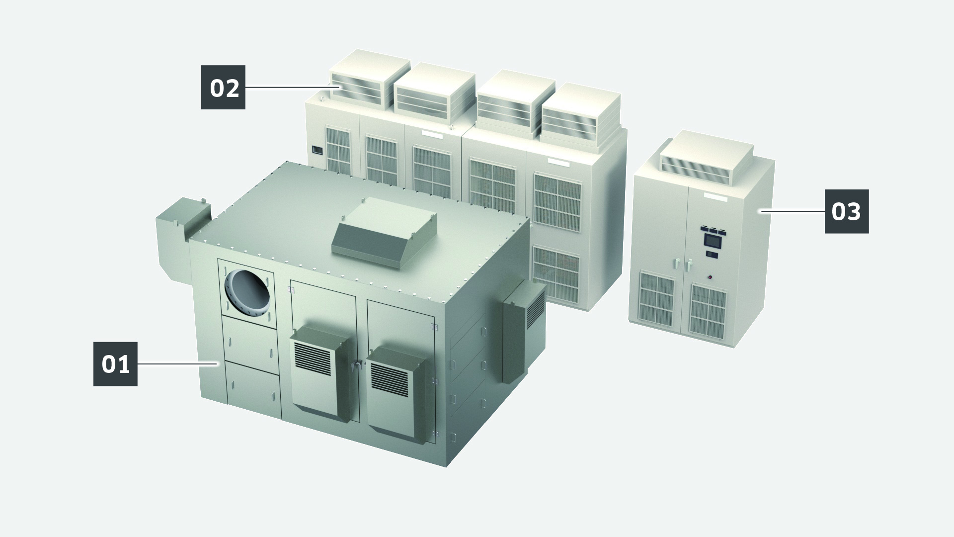
The medium-voltage Variable Frequency Drive (VFD) that drives the high-speed motor also significantly enhances performance. By adopting a fixed pulse pattern method in place of the conventional asynchronous PWM method for the pulse modulation of the cell series multiplexing method normally used for medium-voltage drives, the system achieves the world's highest level of efficiency by suppressing surge voltage, current harmonics, and low-frequency pulsation for higher output and higher frequency. When a plant applies Most Open Valve Control (MOVC), Dual Flow Control significantly enhances energy savings.
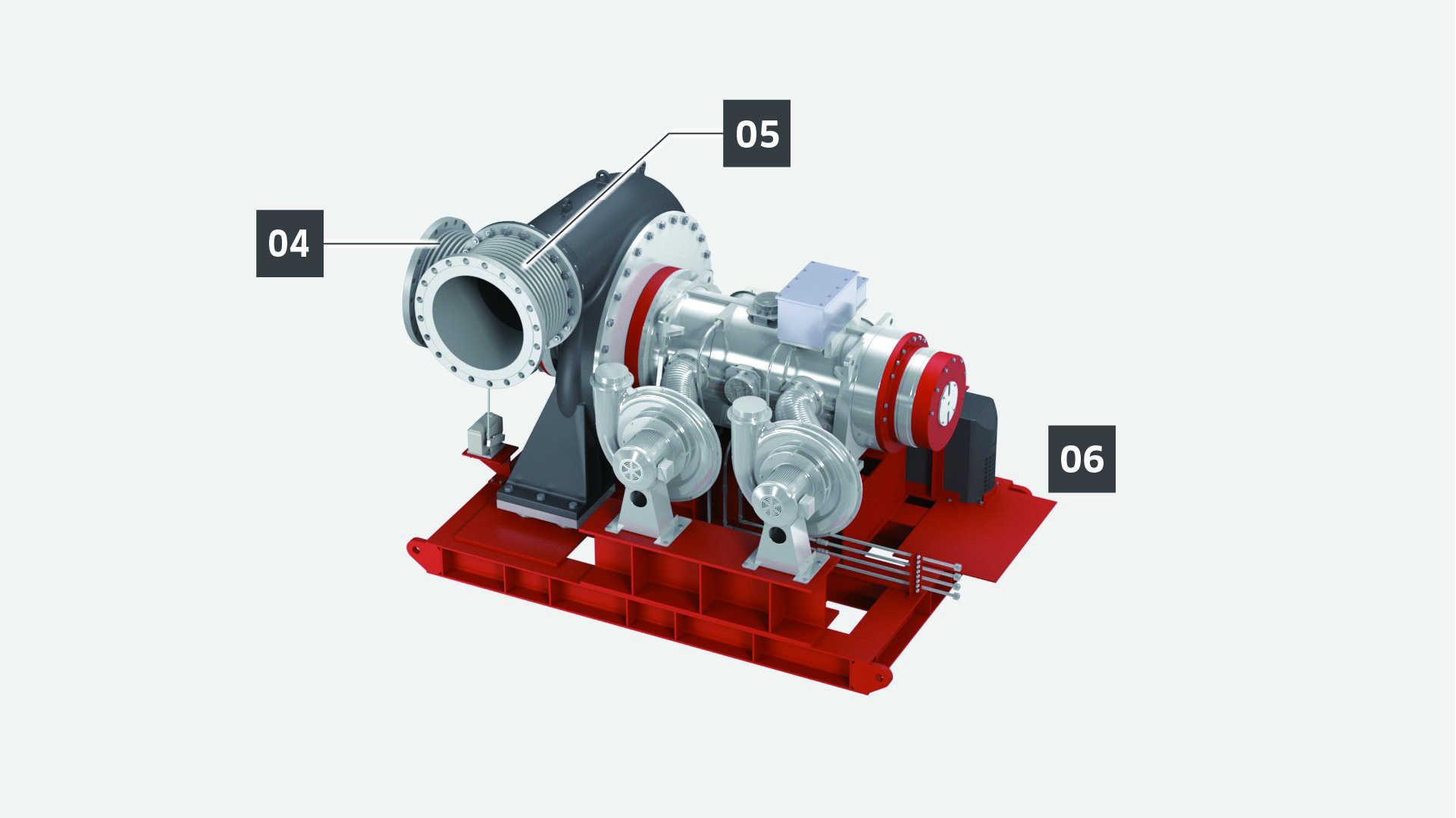
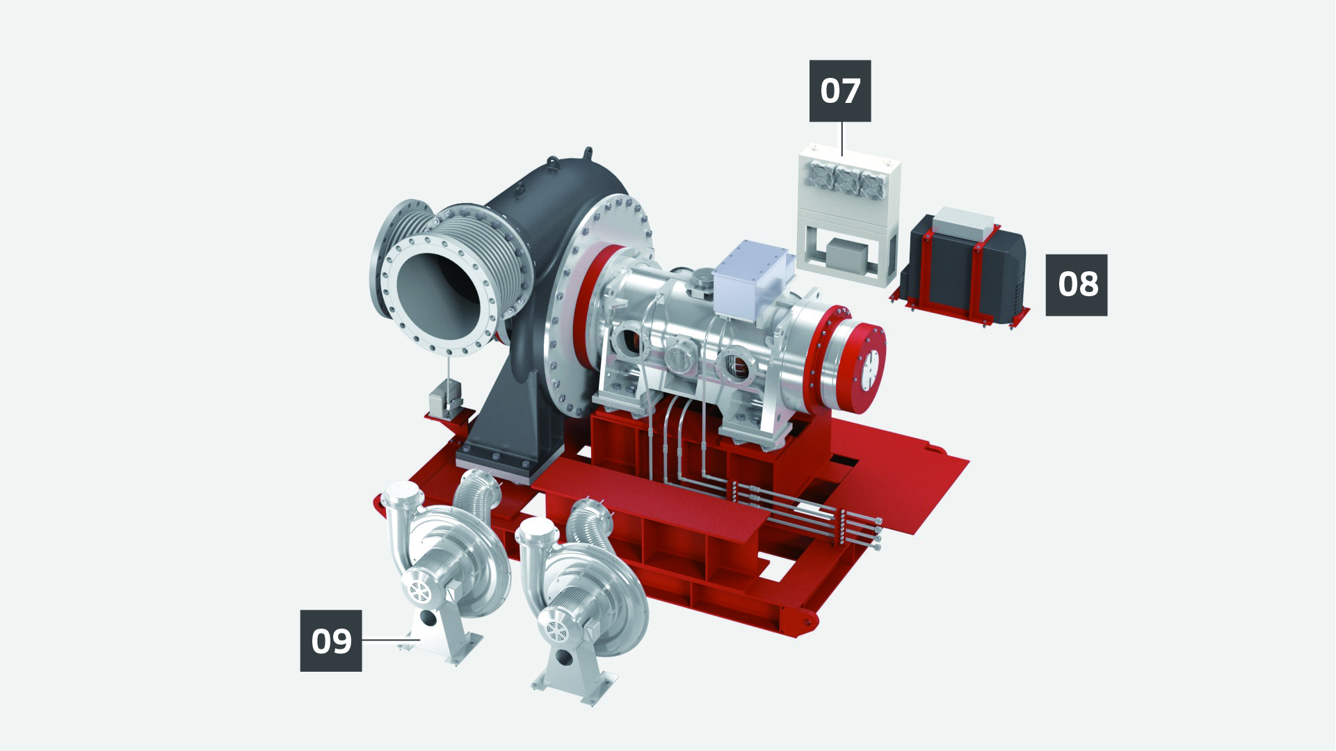
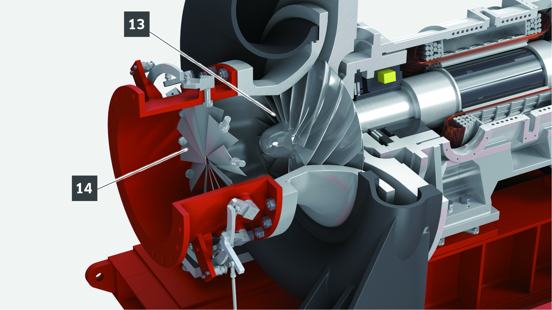
The Inlet Guide Vanes (IGV) are installed upstream of the impeller. The swiveling motion of the vanes pre-whirls the fluid to increase or decrease the work of the impeller and enables to adjust the flow rate and discharge pressure.
Rotational speed control by Frequency Inverter enables to adjust the flow rate and discharge pressure.

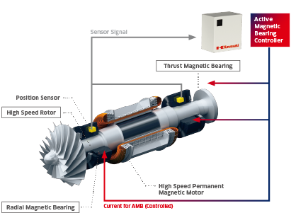
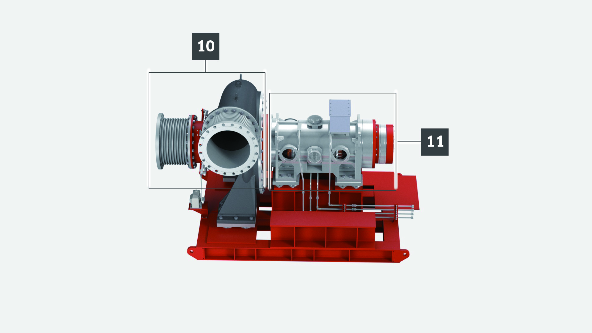
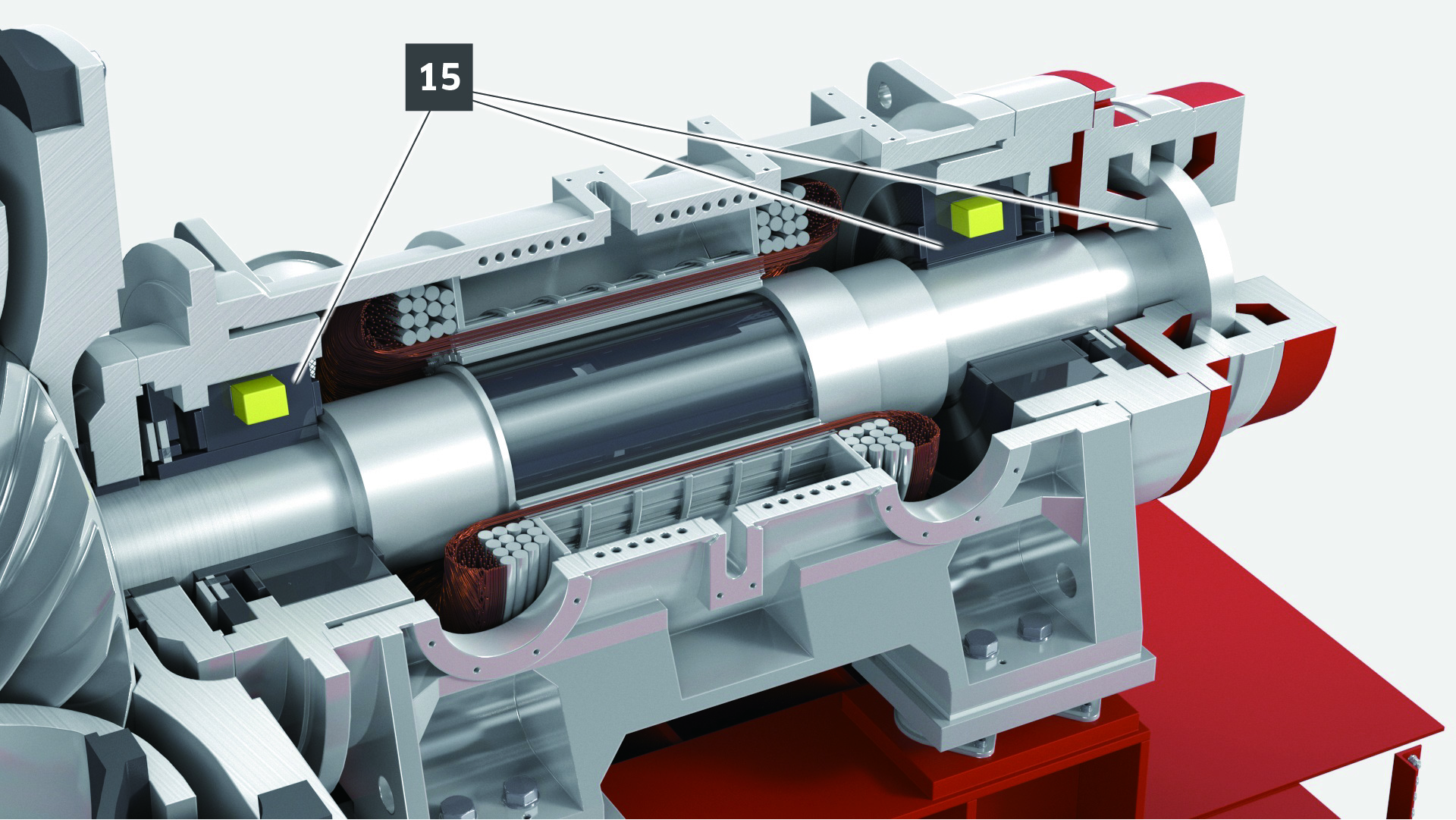
Active magnetic bearings achieve contactless levitation of the rotor using the force exerted by 10 electromagnets. One thrust magnetic bearing and two radial magnetic bearings are used. Two radial magnetic bearings are equipped with sensors which send positional information of X, Y and Z axes to the magnetic bearing controller at the rate of 10,000 times per second to maintain the rotor’s reference position.
This technology, called “High Frequency Feedback Control” developed by Kawasaki, enables stable levitation of a heavy shaft rotating at over 10,000 rpm, with only 20 micrometer of vibration displacement.
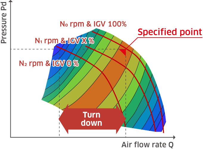
Variable Rotational Speed Control + Inlet Guide Vane Control
Thanks to Combination of “Variable Rotational Speed Control” and “Inlet Guide Vane Control,” highly efficient operation is achievable at any operating point. This is done by optimizing combination of rotational speed and IGV opening in response to fluctuations in flow rate and pressure.


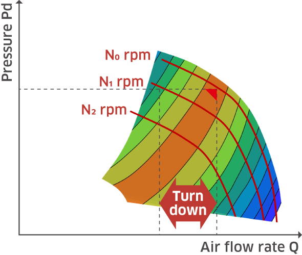
In the case of “Variable Rotational Speed Control”, it is not likely to ensure the required turn down since pressure drop is relatively large due to the relationship of flow rate ∝ rotational speed and pressure ∝ rotational speed2. Offset design, sacrificing efficiency, will be necessary.
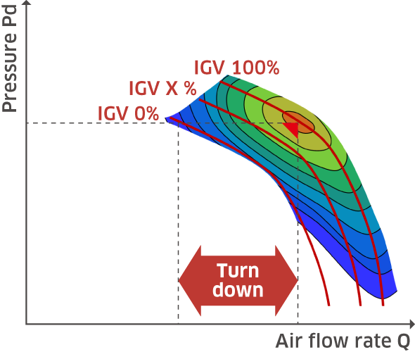
In the case of “Inlet Guide Vane Control”, efficiency drops significantly since the pressure loss at suction side becomes large by closing IGV. Besides, offset design, sacrificing efficiency, will be necessary if the turn down is insufficient.
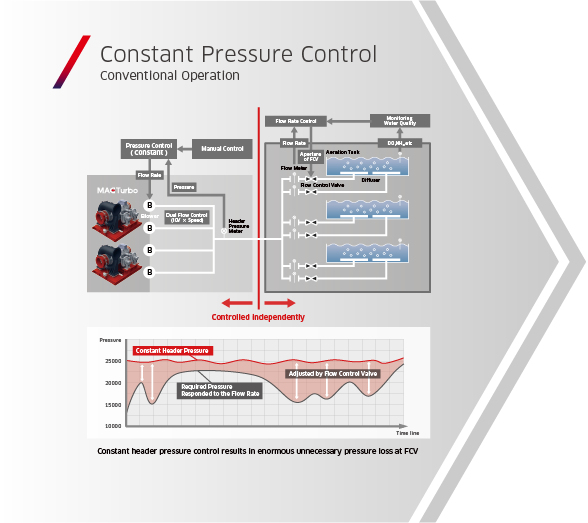
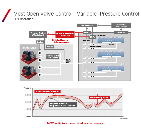
Most Open Valve Control (MOVC) minimizes pressure loss along the process piping by opening the valve for flow control as much as possible. While the normal control method, keeps the pressure in the header piping constant, MOVC allows the header pressure to vary depending on the required airflow rate.
Therefore, the blower for MOVC is required to have the capability to follow this load fluctuation and high efficiency over a wide operating range. The dual flow control of MAG Turbo enables highly efficient operation and fast response control across a broad range of operation conditions. MOVC equipped with MAG Turbo delivers the ultimate power savings.
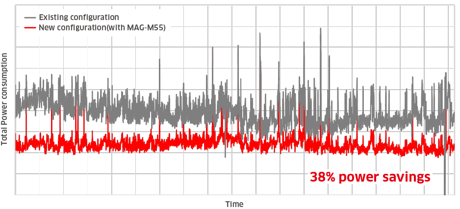
By using MAG Turbo, energy efficiency can be significantly improved, leading to reduced power consumption, as demonstrated in the accompanying graph for example. If customers provide us with transient operating data of existing blower or specific operating conditions, we can simulate the power consumption and demonstrate the potential benefits.
For instance, a reduction of 38% in power consumption is expected in some cases, as shown in the example graph, with the possibility of even greater energy savings in other scenarios. We look forward to your inquiries about improving energy efficiency.

The operation record confirms an Operational Availability of 99.93%. with no downtime attributed to blower-related malfunctions.
In addition to the parts listed in the table, there are standard supply parts and optional parts available upon customer request. For more details, please contact us.
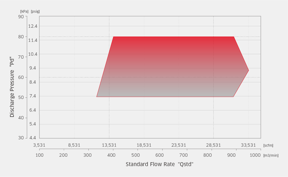
The above range map represents the standard scope of our services. We may also be able to accommodate requests outside the indicated range, so please feel free to contact us.